Pipes
Pipes
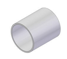
Smap3D Piping does not require 3D geometry to generate a Pipe. Piping needs only two parameters - wall thickness and outer diameter.
Regarding the Standard Parts Provider providing the part, the parameters may be set in the form of characteristics or custom properties.
Even if the geometry is not important for generating pipes itself, it indirectly serves to carry some additional information.
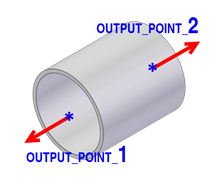
3D geometry may contain OUTPUT_POINT coordinate systems and also CSInfo containing information about connection parameters of the respective pipe end.
This information can be further used for the purposes of Smap3D Piping Design Checks and also for processing in Smap3D Isometric and PCFExport.
The following articles describe a creation process of a pipe usable with Smap3D Piping for various standard parts providers.
How to create a custom pipe (File System Provider)
The recommended way to create a pipe component includes creating the geometry and adding all of the necessary information and attributes using Component Wizard.
The process should look like this:
3D pipe model
Create a 3D model of the pipe in the SOLIDWORKS part environment and save the file.
The model must contain geometry that Coordinate System Wizard can use to position coordinate systems (circle, cylinder or cone surface, or sketch point and sketch segment).
Save the file.
Coordinate Systems, CSInfo and Other Attributes
Start the Component Wizard (from the CAD or Windows Start menu) and go through the steps as follows:
Component type selection - Select Pipe.
Connection points and CSInfo - Gradually, for both coordinate systems select Add to start Coordinate System Wizard. Use it to create the OUTPUT_POINT coordinate systems and specify the desired CSInfo parameters.
Properties - Set values (at least) for the mandatory properties PD_Outer_diameter and PD_Wall_thickness. The values must contain units.
SKEY definition - Keep the SKEY empty (for a common pipe) or set the desired SKEY from the list.
Save component - Set the desired Filename and Location, Finish the wizard and close the part in the CAD application.
Pipe Specification
To set the pipe as part of a pipe specification go through the following steps:Start the Pipe Specification Editor

Open the required pipe specification or create a new one
Add a row, set Key Name to Pipe and select values for the required parameters (check Pipe Specification Editor for details)
Select File System
 and browse for the existing component
Save the pipe specification
 For the purposes of Smap3D Piping (excluding design checks), it is sufficient to use an arbitrary part file (no 3D geometry required) that has PD_Outer_diameter and PD_Wall_thickness custom properties with proper values (numeric value and unit).
How to create a custom pipe (Parts Management)
To create a pipe that can be used by Smap3D Piping and also placed as a variable part via Smap3D Part Finder, it is recommended to go through the following steps.
3D pipe model
Create a 3D pipe model (by extruding) in part environment.
Set a variable (in Equations) to control extruded boss depth.
Save the file.
Start Coordinate System Wizard
 (from the CAD or Windows Start menu) and add two OUTPUT_POINT coordinate systems including the desired CSInfo.
Save the file.
Registering the pipe in the database
Launch the Smap3D Database Administrator, start the Standard Part Assistant and follow the steps of the wizard:
Step 1 - select Add from manual data entry
Step 2 - select the component file
Step 3 - this step is skipped automatically when working with SOLIDWORKS
Step 4 - set an existing or create a new category
The category should contain three characteristics (at least) - two constant (describing the wall thickness and outer diameter) and one variable (controlling the pipe length).
The constant characteristics names should be consistent with those defined for wall thickness and outer diameter in the characteristics file (see Piping Common settings of Plant Design Administrator for details).
To the Variable field of the length-controlling characteristic type the name of the equation used in the 3D pipe model (extruded boss depth).
The row then goes red (to identify a variable characteristic).
For each characteristic set a Unit Class and appropriate unit. In the Properties section there is also the possibility to add (or remove) custom properties.
Step 5 - set values for characteristics and file properties If you select an existing category in step 4, step 6 will be skipped
Step 6 - set a Visual Navigation category (optional)
Step 7 - select Finish to register the component into the database. It is also possible to register the component in the Database via Add part. For the detailed information about Standard Parts Assistant and registering standard parts in general, please refer to the Database Administrator help.
Pipe Specification
To set the pipe as part of a pipe specification go through the following steps:
Open pipe specification or create a new one
Add a row, set Key Name to Pipe and select values for the required parameters (check Pipe Specification Editor for details)
Select Part Finder
 and pick the pipe component in the Part Finder
Start the Pipe Specification Editor
Save the pipe specification
If you do not require to place your custom pipes using different techniques than just automatically via Smap3D Piping, you do not need to create any 3D model (an empty part file is sufficient) and the variable characteristic (pipe length) in Standard Part Assistant.
天津优达思科技有限公司