Couplings
Couplings
The Coupling key name (and the respective QP method) allows automatic placing of straight sockets.
These components connect other components that have socket End Treatment together or with a pipe.
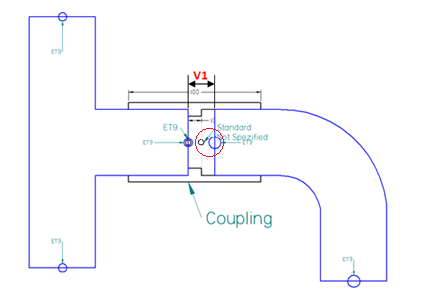
A coupling component must have two pairs of INPUT_POINT and OUTPUT_POINT coordinate systems and corresponding OUTPUT_AXIS for each of them.
CSInfo of one of the OUTPUT_POINT coordinate systems must have set Socket End Treatment (ET=9).
The other OUTPUT_POINT coordinate system must have Unspecified End Treatment (ET=0).
The distance between the OUTPUT_POINT coordinate systems must be at least 0,01 mm (approx. 0.004").
 The proper coordinate systems and axes as well as the CSInfo can be created easily using Coordinate System Wizard.
In practice, the typical situation is that a coupling should connect two fittings whose distance (distance between their OUTPUT_POINT coordinate systems with Socket End Treatment) is greater then the distance of OUTPUT_POINT coordinate systems within the coupling component.
Depending on the components distance and the coupling component definition, the situation can be correctly solved in two different ways:
one coupling is placed that connects both components.
two couplings are placed (one at the end of each component) and a pipe is generated between them.
For the Piping to automatically recognize the proper situation, the coupling components must have set two additional parameters:
CT_1 (one coupling tolerance) is the largest distance of the component ends where just a single coupling is placed. CT_1 must be greater than the distance of OUTPUT_POINT coordinate systems within the coupling component (and should be shorter than the total length of the coupling).
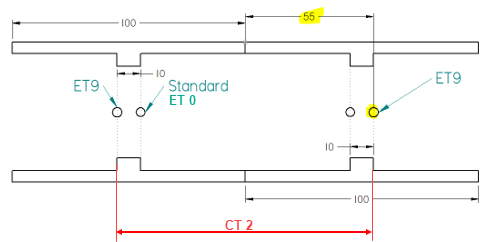
CT_2 (two couplings tolerance) is the smallest distance of the component ends where two couplings (and a pipe) are placed. The minimum value for CT_2 is twice the CT_1 value. In practical terms, the CT_2 value should be derived from the coupling component geometry. It should be at least twice the distance between the socket End Treatment OUTPUT_POINT coordinate system and the opposite coupling end.
The CT_1 and CT_2 must be set as custom properties of the coupling CAD file. The text values must be composed of a numerical value and a unit separated by a space (e.g. 20 mm).
Example:
If two components are not close enough together, two couplings (with a connecting tube) can be generated to cover the free space.
For this purpose it is necessary to define the CT_2 property in the coupling component, which defines the minimum distance between the coordinate systems with ET=9 and the farther edge of the coupling for the correct placement of both couplings and a pipe.

天津优达思科技有限公司